Control Systems Laboratory
Room E2.01
Brunnenlech Campus
Tel. +49 821 5586-5070
Goals
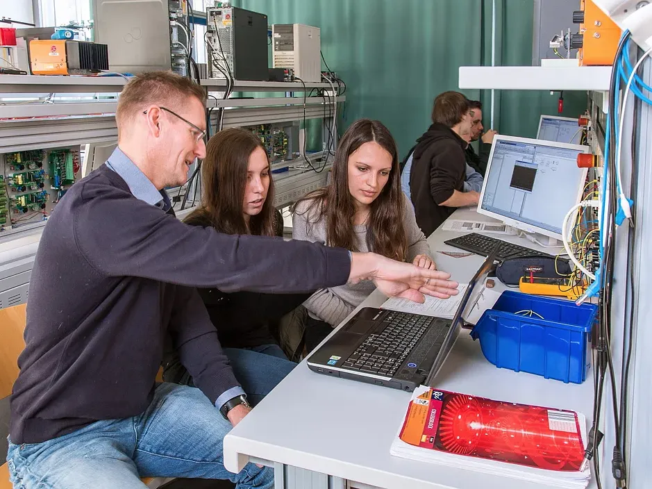
The introductory laboratory course teaches bachelor’s students in electrical engineering and mechatronics the fundamentals of control engineering and dynamic systems. The methods covered in the lecture are applied experimentally, through simulation, and using real test setups.
In particular, students learn:
- how to experimentally investigate, model, and describe dynamic systems using transfer functions,
- to design P, PI, PD, and PID controllers using various methods and to optimize their parameters,
- to build and commission analog and real-time control loops,
- to implement current, speed, and angle control as well as cascaded control structures,
- to evaluate measurement data and compare measurement, model, and simulation results,
- to conduct experiments in a structured manner as a team and to document the results in a technical report.
Events
Control Engineering Module
The lab is part of the Control Engineering module in the bachelor programs in Electrical Engineering and Mechatronics. The module is offered in both the winter and summer semesters and includes the Control Engineering lecture (four semester hours per week), a 90-minute exam, and the accompanying introductory lab. The lecture, exam, and lab together constitute the complete module.
Introductory Lab in Control Engineering and Dynamic Systems
The lab consists of five lab days, each with approximately three hours of lab time. Two to three students work together at each workstation.
Experiment Days 1 and 2: Analog System Models and Real-Time Control
- Analog plant models based on operational amplifier circuits
- Combination of up to three PT1 elements
- Analog PID controller with parameters adjustable via potentiometers
- Implementation of controllers on a computer using Simulink Real-Time
- Connecting the experimental setups via the analog inputs and outputs of a real-time interface
- Measurement data acquisition and data analysis in a preconfigured Simulink model with a sampling time of 5 ms
Experiment Days 3 through 5: Control of a DC Motor
- Investigation and control of a physical DC motor at each workstation
- Current control, speed control, and phase angle control
- Cascaded control structures up to a triple cascade consisting of an internal current control loop, a speed control loop, and an external angle control loop
- Design and optimization of P, PI, PD, and PID controllers
- Application of, among others, the Ziegler-Nichols method, the turning-tangent method, and the minimum-absolute-value method
- Measurement-based identification of the transfer function of the DC motor using the System Identification Toolbox
- Controller design and optimization using the Control System Designer or the SISO tool in MATLAB
- Application of the controllers to a real DC motor and comparison of measured and simulated waveforms
Course Assessment
A single lab report covering all five days of the experiment must be prepared and submitted. The lab is graded as “pass” or “fail” and, together with the lecture and exam, is part of the Control Engineering module.
Features
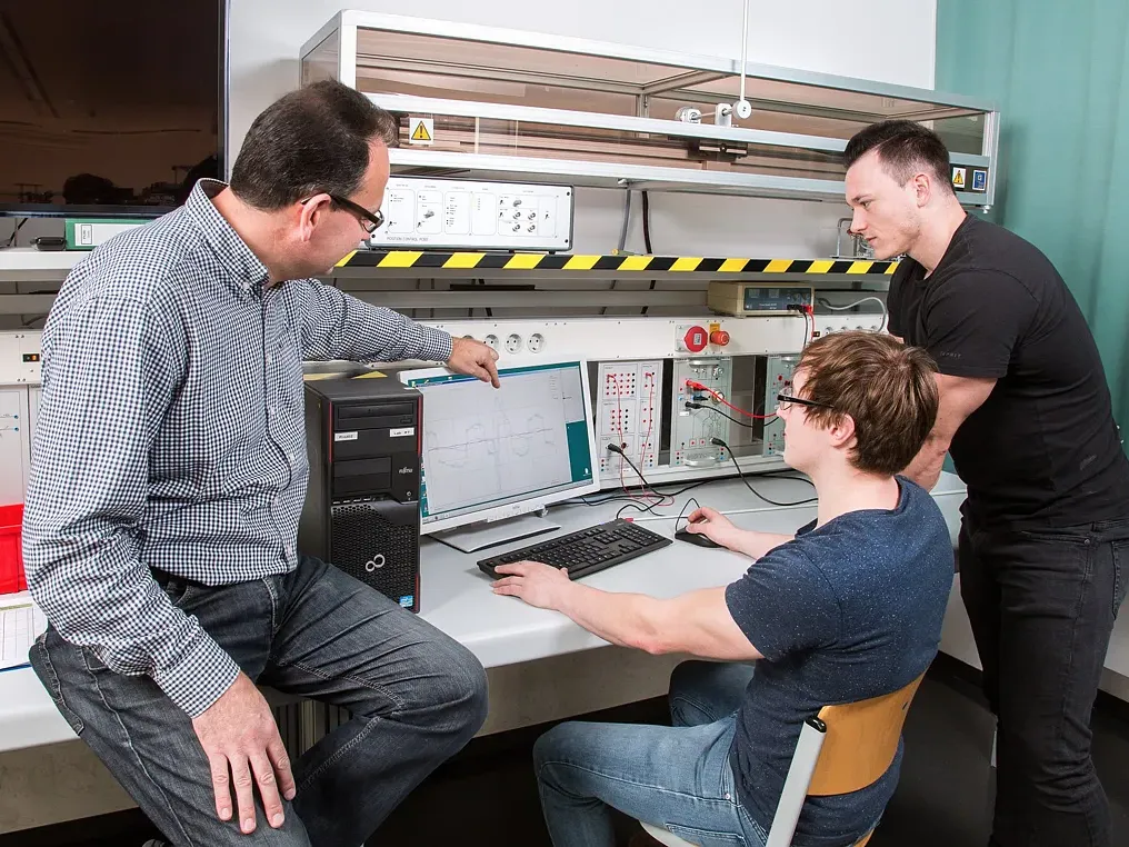
Experimental workstations for groups of two to three students each
Analog circuit models in the form of operational amplifier circuits
Up to three PT1 elements per workstation that can be combined with one another
Analog-adjustable PID controllers with potentiometers
Real-time interfaces with analog inputs and outputs
Computers with Simulink Real-Time and preconfigured Simulink models for measurement data acquisition and analysis
Measurement data acquisition with a sampling time of 5 ms
Physical DC motor at each workstation
MATLAB and Simulink, including Control System Designer and the System Identification Toolbox
Projects
Projects in the Control & Automation Module